

Which Of The Following Drawing Components Are Not Commonly Drawn In Paper Space
Display one or more scaled views of your design on a standard-size cartoon sail called a layout.
Afterwards you finish creating a model at full size, you can switch to a newspaper infinite layout to create scaled views of the model, and to add notes, labels, and dimensions. You tin can also specify different linetypes and line widths for display in paper space.
Specifying the Paper Size of a Layout
The commencement matter that you should do when you access a layout tab (1) is correct-click the tab (2) and rename it (3) to something more specific than Layout ane. For a D-size layout, ARCH D or ANSI D might be a good choice.
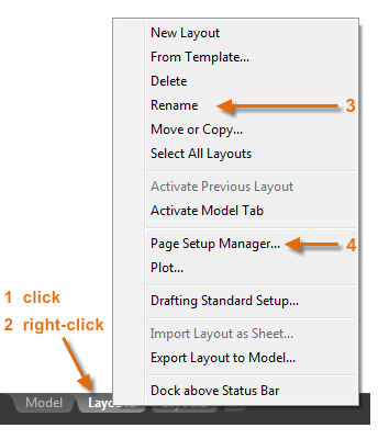
Next, open the Page Setup Director (four) to alter the paper size displayed in the layout tab. At that place are a lot of controls hither, but y'all simply need to change a few. The beginning is to specify the size of your sheet.

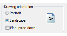
Notation: You might be wondering why in that location are two entries in the list for every sheet size. This is because some printers and plotters do not recognize the drawing orientation setting.
Model Space and Paper Space
Equally yous know, you create the geometry of your model in model space.
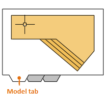
Originally, this was the just space available in AutoCAD. All notes, labels, dimensions, and the drawing border and title block were also created and scaled in model space. For some applications, this method is nonetheless entirely sufficient.
With the newspaper space feature, you can click a layout tab designed specifically for displaying multiple views, automatic scaling, and electronic or printing output.
For example, a layout tab is selected in the following analogy. In that location are currently two objects in paper infinite: a block object for the championship and drawing border, and a unmarried layout viewport, which displays a scaled view of model space.
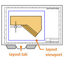
By default, a single layout viewport object is initially included on each layout tab, only your organization might exist using customized drawing template (DWT) files that include several predefined layouts, layout viewports, and title blocks.
Let'southward learn more about layout viewport objects.
Layout Viewports
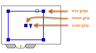
A layout viewport is an object that'due south created on a layout tab to display a scaled view of model space. You can think of it as a closed-circuit TV monitor that displays part of model infinite. You can select a layout viewport as y'all would any other object. When you select it, several grips display that provide a way to accommodate the size of the viewport, move the viewport, and specify the scale of the view that's contained in it.
Several editing commands such every bit Move, Erase, and Copy can be used on layout viewports. When you select a layout viewport, you lot can use the Properties palette to provide a complete list of options and settings.
Tip: When y'all're set to create an electronic output or print a layout, you will want to hide the viewport borders. To accomplish this, create all viewport objects on a carve up layer and then turn that layer off.
Switch betwixt Model Space and Paper Space
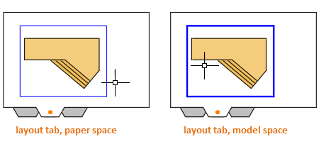
When you're working on a layout tab, you can switch between paper space and model infinite without returning to the Model tab. Hither'southward how. Every bit shown in the illustration, you movement your cursor and double-click either inside a layout viewport to admission model space or you lot double-click exterior the layout viewport to return to paper space. When you lot're in model space, the edge of the layout viewport becomes thicker.
The primary reasons that you might want to access model space through the layout viewport is to pan the view or to make pocket-size adjustments to the objects, specially those that display only in that viewport.
Tip: Instead of panning a view, simply select the viewport object from paper space, click one of the four size grips, and adjust the boundary.
Create a New Viewport
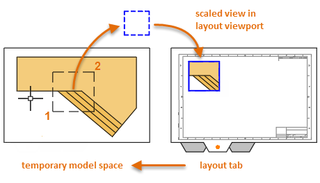
You can use the New choice of the MVIEW (make view) command to create boosted layout viewports in paper space. With several layout viewports, y'all can brandish unlike views of model space at the same scale or at unlike scales.
- From a layout tab, enter MVIEW in the Command window and cull the New pick.
- A maximized view of model space displays temporarily and you tin click two points every bit shown to ascertain an area.
- Back in the layout, right-click to display a listing of scales and click the one that you want to use.
- Click a location to place the new layout viewport containing the scaled view.
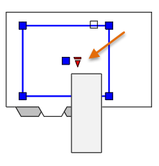
If you later need to fix a different scale, select the layout viewport and click the triangular scale grip. This action displays a listing of scales to choose from.
By default, scaled viewports are automatically locked to forbid adventitious zooming or panning, which would change the scale or the clipping boundaries. You can lock and unlock a layout viewport past selecting it, right-clicking to brandish the shortcut menu, and choose Display Locked > On or Off.
Note: As required by drafting conventions, the dashes and spaces in a non-continuous linetype always announced at the aforementioned length regardless of the scale of the layout viewport. If you change the scale of the layout viewport, you will need to enter REGENALL to update the display immediately.
Trans-Spatial Notation
Subsequently you lot create one or more than scaled layout viewports on a layout tab, follow these steps to utilise the trans-spatial method of annotating your drawing:
- Movement the layout viewport as needed, and suit its edges using the size grips.
- Plough off the layer on which y'all created the layout viewport object. This hides the edges of the layout viewport.
- Create notes, labels, and dimensions directly in newspaper space. They automatically appear at the correct size.
- Print the drawing to newspaper or as a DWF or PDF file.

Four Methods for Scaling Views and Annotating Drawings (Optional)
There are four different methods in AutoCAD for scaling views, notes, labels, and dimensions. Each method has advantages depending on how the drawing will be used. Hither'southward a cursory summary of each of the methods:
- The Original Method. You create geometry, comment, and impress from model space. Dimensions, notes, and labels must all be scaled in contrary. Y'all set the dimension scale to the inverse of the plot scale. With this method, scaling requires a little math. For case, a usually used imperial scale in compages is 1/4" = 1'-0" which is 1:48 scale. If a note is to exist printed one/4" high, then information technology must be created 48 times as large, or 12" high in model space. The same scale factor as well applies to dimensions, and an ARCH D drawing border at that scale is 144 feet long. When the drawing is printed as a D-size sail, everything scales down to the right size.
Note: Many AutoCAD drawings were created with this method, and many companies still utilise it. In one case everything is gear up up, the method works well for 2nd drawings with single views and inserted details.
- The Layout Method. Yous create geometry and annotations in model space, and then print from the layout. Set the dimension scale to 0 and the dimensions will calibration automatically.
- The Annotative Method. You create geometry in model space, create annotative dimensions, notes, and labels, which utilise a special annotative manner, in model space from the layout, then you lot impress from the layout. Annotative objects display only in layout viewports that share the same calibration. The dimension scale is automatically prepare to 0 and all annotative objects scale automatically.
- The Trans-Spatial Method. You create geometry in model space, create annotations in paper infinite on a layout with the dimension calibration set to one, and then you impress from the layout. This is arguably the simplest, most directly method, which is why it is the method of choice for this guide.
Tip: Talk to other AutoCAD users in your discipline nearly these four methods and why they chose the method that they utilise.

Source: https://knowledge.autodesk.com/support/autocad/learn-explore/caas/CloudHelp/cloudhelp/2018/ENU/AutoCAD-Core/files/GUID-DF5C5E9A-113E-456E-AFC4-4CEDAEE60A78-htm.html
Posted by: thibaultdianow.blogspot.com
0 Response to "Which Of The Following Drawing Components Are Not Commonly Drawn In Paper Space"
Post a Comment