

How To Draw Tikz Diagram For Ieee Papers
Part one | Office ii | Part 3 | Part four | Part v
Author: Josh Cassidy (August 2013)
This five-part series of manufactures uses a combination of video and textual descriptions to teach the basics of creating LaTeX graphics using TikZ. These tutorials were starting time published on the original ShareLateX blog site during August 2013; consequently, today's editor interface (Overleaf) has changed considerably due to the development of ShareLaTeX and the subsequent merger of ShareLaTeX and Overleaf. Notwithstanding, much of the content is withal relevant and teaches y'all some basic LaTeX—skills and expertise that will apply across all platforms.
Additionally, TikZ libraries and methods for positioning nodes have changed over the years. If yous're learning TikZ today, it's best to employ the positioning library to identify your nodes with below=of-style syntax. The positioning library syntax is more flexible and powerful. The older beneath of=-style syntax used in the video and examples below is officially deprecated simply volition withal work. Additionally, the arrows library is now deprecated in favor of the newer arrows.meta library. Other TikZ commands and libraries used here may have more mod equivalents. Until nosotros produce a new video tutorial, we'll go on the code examples as-is so they correspond with the video content.
In this post we're going to be looking at creating flowcharts in TikZ. To become started we need to load up the tikz packet, the shapes.geometric TikZ library and the arrows library.
\usepackage {tikz} \usetikzlibrary {shapes.geometric, arrows} The tikzstyle command
At present earlier nosotros showtime the document we need to define the basic components of a flowchart. To do this nosotros use the \tikzstyle command. First, let's ascertain the cake we're going to use for beginning and stop blocks. We'll proper name it startstop using curly brackets immediately following the control, and so we add together an equals sign before a set of square brackets. In the square brackets we enter all the formatting data. For this block we'll specify a rectangle with rounded corners. We'll give it a minimum width of 3cm and a minimum acme of 1cm. We'll also ensure the text gets centred and nosotros'll set both a draw and a fill colour. In this example we've set the fill colour to a colour that is thirty% cherry mixed with 70% white:
\tikzstyle {startstop} = [rectangle, rounded corners, minimum width=3cm, minimum height=1cm,text centered, depict=black, fill=red!xxx] Next we'll specify an input or output box. This time we want the block to be a parallelogram. To achieve this we inquire for a trapezium and and so change the angles. The rest is very similar:
\tikzstyle {io} = [trapezium, trapezium left angle=70, trapezium right angle=110, minimum width=3cm, minimum height=1cm, text centered, depict=black, make full=blue!30] Adjacent nosotros'll add together a \tikzstyle for process blocks using a rectangle and a style for decision blocks using a diamond:
\tikzstyle {procedure} = [rectangle, minimum width=3cm, minimum height=1cm, text centered, draw=black, fill=orange!30] \tikzstyle {decision} = [diamond, minimum width=3cm, minimum meridian=1cm, text centered, draw=blackness, fill=green!30] Finally nosotros'll define a style for the arrows. For this we set the line thickness to thick, add an pointer caput and specify the stealth arrow head:
\tikzstyle {arrow} = [thick,->,>=stealth] Nodes
Now we are set up to get-go building our flowchart. To do the we utilize the tikzpicture environment. Nosotros'll create our flowchart blocks using nodes and the tikzstyles nosotros divers earlier. Nodes are very powerful as we can easily position them, brand them describe a shape, heavily format them and give them some text. In square brackets at the finish of the begin command we specify a node distance of 2cm. This is so that the nodes nosotros apply to build the blocks are automatically spaced 2cm apart from their centres:
\begin {tikzpicture}[node distance=2cm] <TikZ lawmaking> \end {tikzpicture} To add a node we employ the \node command. We then add together a label for the node in parenthesis. This label is how we refer to the node in the rest of the lawmaking. And then in square brackets we add the proper name of the \tikzstyle we want the node to conform to, forth with any other formatting options. Then in curly brackets nosotros add the text we want to appear in the block before endmost the statement with a semicolon:
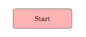
\node (start) [startstop] {Kickoff}; If nosotros at present compile the lawmaking y'all'll see our start block has appeared as expected:
Now allow's add an input block in below the start block. This fourth dimension we demand to tell the node where to position itself. To do this we enter below of followed by an equals sign and a node label into the foursquare brackets. Nosotros could as well use higher up of, right of or left of if we wanted the block to appear somewhere else. We'll tell information technology to position itself below the start block:
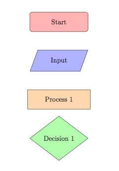
\node (in1) [io, beneath of=offset] {Input}; Now lets add in a process block and a decision block.
\node (pro1) [process, beneath of=in1] {Procedure 1}; \node (dec1) [decision, below of=pro1] {Conclusion 1}; If we compile the lawmaking you'll notice that the gap between the dark-green decision block and the orange process cake isn't as large as the other gaps:
This is because the decision block, being a diamond, is taller than the other blocks. Therefore we can manually arrange its position using the yshift variable. If we enter yshift=-0.5cm information technology volition move the decision block vertically down by 0.5cm which should make the gap more regular:
\node (dec1) [decision, below of=pro1, yshift=-0.5cm] {Decision 1}; 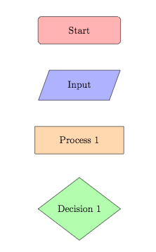
Now lets add together in two process blocks coming out of the determination cake, i below it and one to the correct of it. Again, we'll need to alter the positioning using yshift for the block below and xshift for the block to the right. Let's finish off adding the blocks by adding in an output block and a cease cake.
\node (pro2a) [process, beneath of=dec1, yshift=-0.5cm] {Process 2a}; \node (pro2b) [procedure, correct of=dec1, xshift=2cm] {Process 2b}; \node (out1) [io, below of=pro2a] {Output}; \node (stop) [startstop, beneath of=out1] {Stop}; 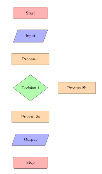
Arrows
To finish off our flowchart we need to add the arrows in. To draw an arrow we utilize the \draw command and and so specify the tikzstyle we prepared for arrows using square brackets. We then enter the characterization of the node we want the arrow to start from, followed by ii dashes and and then the characterization corresponding to the node we desire the arrow to terminate at. The labels need to be in parenthesis and nosotros need to make sure we close the statement with a semicolon. Lets add arrows in between the outset block and the input block, the input and process 1, process 1 and conclusion 1, decision 1 and process 2a and between decision 1 and process 2b:
\depict [pointer] (start) -- (in1); \depict [arrow] (in1) -- (pro1); \depict [arrow] (pro1) -- (dec1); \depict [arrow] (dec1) -- (pro2a); \draw [pointer] (dec1) -- (pro2b); 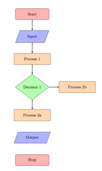
As nosotros have arrows coming out of a decision cake we demand to add some text to these two arrows. To exercise this we utilise more nodes, however this time we don't need to apply the \node control, nosotros but type the give-and-take node in afterwards the two dashes and and then the text in curly brackets:
\draw [pointer] (dec1) -- node {aye} (pro2a); \depict [arrow] (dec1) -- node {no} (pro2b); If we now compile the code you'll see the text has been added but non in a very helpful place:
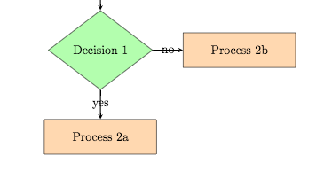
To set up this nosotros specify which of the node'south anchors TikZ should use to set the nodes to the lines. To practise this we employ square brackets immediately after the keyword node and then enter anchor= followed by the anchor. For the yes node we'll use the east anchor and for the no node we'll use the south anchor:
\draw [pointer] (dec1) -- node[anchor=east] {yes} (pro2a); \describe [arrow] (dec1) -- node[anchor=south] {no} (pro2b); 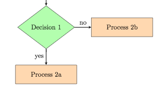
Now let'south draw the terminal arrows in:
\draw [arrow] (pro2b) -- (pro1); \draw [pointer] (pro2a) -- (out1); \describe [arrow] (out1) -- (stop); 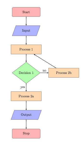
You'll also notice that the arrow from process 2b to process 1 is diagonal and therefore doesn't look correct. To better this we can swap the first dash for a bar symbol which will brand the arrow go in a vertical direction before going in a horizontal direction:
\depict [arrow] (pro2b) |- (pro1); 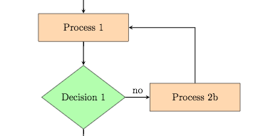
Text width
The final thing nosotros should discuss is the text width. At the moment all our text fits nicely inside our shapes. Notwithstanding, if for case, we add some more text to procedure 2a, you'll see the shape just extends horizontally until the text fits:
\node (pro2a) [process, below of=dec1, yshift=-0.5cm] {Procedure 2a text text text text text text text text text text}; 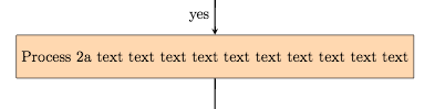
This now becomes a bit messy. To improve information technology nosotros can specify the text width for these nodes by entering text width= followed by a length into our \tikzstyles:
\tikzstyle {process} = [rectangle, minimum width=3cm, minimum summit=1cm, text centered, text width=3cm, draw=black, fill=orange!xxx] 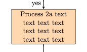
This concludes our post on creating flowcharts with TikZ. If you want to play around with the flowchart we created in this post you tin can access it here. In the adjacent post we'll wait at drawing electric circuits.
All articles in this series
- Part 1: Bones Cartoon;
- Role 2: Generating TikZ Code from GeoGebra;
- Part three: Creating Flowcharts;
- Part 4: Circuit Diagrams Using Circuitikz;
- Office 5: Creating Mind Maps.
Please do keep in affect with us via Facebook, Twitter or via email on our contact us page.

Source: https://www.overleaf.com/learn/latex/LaTeX_Graphics_using_TikZ:_A_Tutorial_for_Beginners_%28Part_3%29%E2%80%94Creating_Flowcharts
Posted by: thibaultdianow.blogspot.com
0 Response to "How To Draw Tikz Diagram For Ieee Papers"
Post a Comment